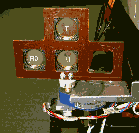
Figure 1 Transmitter and receivers (labeled as T, R0 and R1) are 40 mm between centres in the sonar sensor.
Lindsay Kleeman
Intelligent Robotics Research Centre
Department of Electrical and Computer Systems Engineering,
Monash University, Australia
Key words: ultrasonic, sonar, tracking, interference rejection, bearing.
Abstract
A new approach to rejecting interference between sonar systems is presented in this paper. The approach is based on identifying a transmitter by sending a double pulse with known separation. Using simple delayed pulse subtraction, a sonar receiver can test echo pulses quickly and simply for acceptance. This approach is implemented on a sonar system that is capable of accurately tracking objects at measurement rates exceeding 10 Hz. Two sonar sensors, each consisting of a transmitter and two receivers, are independently controlled to track objects from bearing and range measurements. Matched filtering is used to optimally estimate echo arrival times from which range and bearing angle are derived. Bearing accuracy is typically better than 0.1 degrees but degrades if there is air turbulence and temperature gradients. Bearing errors are shown experimentally to have significant autocorrelation at times of the order of seconds. The ability to reliably reject interference is demonstrated experimentally by both sensors simultaneously tracking the same plane object.
Introduction
There are many environmental sensing options available on mobile robots for application to localisation, map building and obstacle avoidance. Active sensing approaches such as laser range finders, stripe light ranging, infra-red sensors, short wave radar and sonar offer advantages in accuracy, robustness and simplicity compared to passive sensor systems such as stereo vision and passive infra-red sensing. In a sonar system, range is estimated by measuring the time of flight of a transmitted acoustic signal. Bearing can be estimated from the difference in arrival times at two receivers, as in this paper, or less accurately by examining echo amplitudes from multiple readings at different angles (Kleeman, 1996).
A common problem with active sensing is interference between sensors deployed concurrently. This paper addresses the interference problem in sonar sensing by reliably rejecting interference between two or more sensors. The technique requires minimal computational overhead and just one measurement. Other work on sonar interference (Borenstein and Koren 1995) has employed alternating firing patterns to statistically eliminate crosstalk problems, but requires more than one measurement cycle. Pseudo random pulse sequences also have been used (Jorg and Berg 1998), but incur a significant processing overhead and require long pulse sequences.
Despite the appearance of sonar systems capable of angle measurement and target classification (Stevens et al 1995, Kleeman and Kuc 1995, Yata et al 1998, Peremans et al 1993, Kuc 1993), there is still a perception that sonar sensing is unreliable and inaccurate for measuring bearing (Budenske and Gini 1994, Tsubouchi 1996). This is due mainly to inappropriate modelling that neglects fundamental wave physics (eg specularity and diffraction), crosstalk in sonar rings and poor sensor configurations. One sensor configuration is the popularly deployed Polaroid Ranging Module (Lee 1996, Tsubouchi 1996) which has particularly poor bearing accuracy due to the reliance on the transducer beamwidth alone for angular discrimination. In fact one of the greatest assets of sonar is its bearing measurement accuracy and this will be shown in this paper. The other advantage of sonar sensing compared to shorter wavelength vision based systems is that the specularity of ultrasound in indoor environments naturally selects reliable map features such as smooth walls, corners and edges that are usually sparsely distributed in the environment. By using these natural beacons, accurate feature maps have been built while simultaneously localising to the features as the map is built (Chong and Kleeman 1997).
This paper describes two new ultrasonic object trackers that are mounted on a mobile robot for a real time localisation and map building research project. One application of the sonar sensors is to quickly seek out and lock onto reliable ultrasonic reflectors in the environment as the robot moves, similar to the sonar trackers in OxNav (Stevens et al 1995) and a 3D tracker (Kuc 1993). However, the sonar sensor system presented here produces significantly more accurate bearing angle estimates and reliably rejects crosstalk and interference. The sonar system is unique in that it employs sonar echo amplitude and pulse shape to select good objects for localisation.
Each of the two sonar sensors has a single transmitter and two separate receivers implemented with Polaroid 7000 electrostatic transducers. Although it is possible to use a single transducer as a transmitter and receiver, a better signal to noise ratio is obtained by separating the two. Conventional wisdom suggests that greater bearing angle accuracy can be obtained by wider separation of the receivers (Peremans et al 1993). Just the opposite approach is adopted here for several reasons:

Figure 1 Transmitter and receivers (labeled as T, R0 and R1) are 40 mm between centres in the sonar sensor.

The sonar tracker orientation is controlled by a DC motor and gearbox with optical encoder feedback from the pan angle to a MC1401 PID controller (Performance Motion Devices 1995). The encoder resolution is 0.18 degrees. The pan angle is driven at speeds of up to 360 degrees per second for rapid positioning.
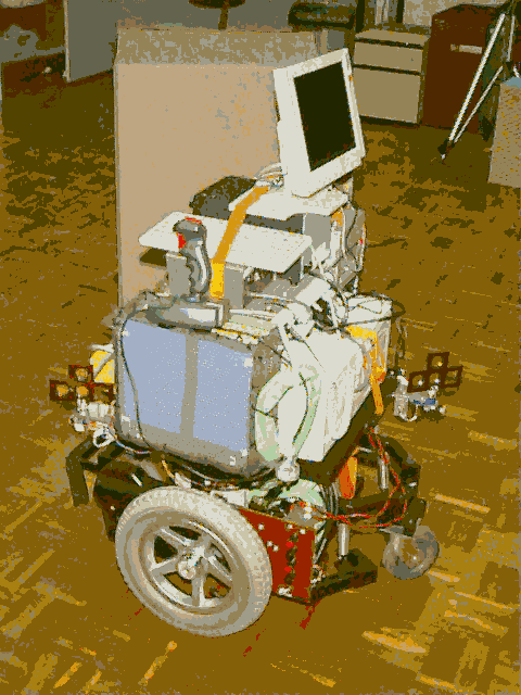
Two sonar trackers are deployed on the robot at the front left and rear right as shown in Figure 2. This enables complete object "visibility" around the robot.
Data Acquisition and Transmit Hardware
The sonar echoes are sampled synchronously at 1 MHz and 12 bits on each of the four receivers and transferred to processor memory in real time with PCI bus DMA. A Pentium processor is then free to execute code whilst sonar data is transferred to memory. The analogue front-end of one receiver is shown in Figure 3, and consists of a low noise preamplifier and variable gain amplifier. The variable gain amplifier prevents saturation for near objects and provides adequate gain for long range objects and allows ranging from 0.07 to 8 metres. As echoes are received, the gain is read from onboard RAM memory feeding a DAC and low pass filter, allowing the gain profile to be adjusted in software. A 4th order low pass filter removes most receiver noise above 110 kHz for anti-aliasing and thresholding purposes in data processing.
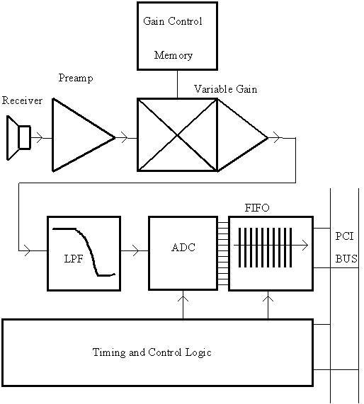
Figure 3 - Receiver interface and data acquisition circuitry for one receiver.
The transmitter excitations are stored in onboard RAM so that the transmitted pulse shape is programmable. The double pulse coding scheme is implemented this way. One transmitter pulse which consists of a few cycles at 55 kHz, is approximately 80 microseconds duration (about 27 mm distance of flight in air). Such a short pulse allows fine object discrimination of the order of 15 mm separation in range which corresponds to 30 mm extra distance of flight of the ultrasonic pulse.
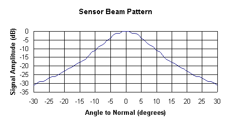
Figure 4 – Sensor beam
pattern by combining transmitter and receiver beam patterns produced by
the 80 microsecond broad bandwidth pulse.
The receiver signal peak to noise standard deviation ratio (SNR) of an echo from a perpendicular smooth wall at 1 metre range is approximately 50 dB. The SNR when the transmitter and receiver are not pointing directly at the wall is reduced by the sensor beam pattern as can be seen in figure 4. Due to thresholding in the signal processing at 7 noise standard deviations, 17 dB SNR is required to detect an echo pulse which means the wall at 1 metre can be detected up to 30 degrees off axis (see figure 4). As range increases, the echo amplitude is attenuated by geometric spreading of the transmitted energy (signal inversely proportion to range) and frequency dependent absorption losses in air (around 1 to 3 dB/metre depending on temperature and humidity). This results in an effectively maximum range of typically 8 metres for a smooth perpendicular wall (at 1 metre range we have 33 dB SNR and lose 18 dB due to 1/8 signal goemetric spreading and a further 15 dB of absorption losses at 2.14 dB per metre). This approximate analysis can be applied to estimating the effective sensor beam width as a function of range and absorption losses.
Note that the beam pattern in figure 4 has no side lobes that are often seen in ultrasonic transducer data sheets. This results from the use of a short transmitter pulse which has a broad bandwidth of approximately 20 kHz. Side lobes are a result of interference at a particular frequency and their position varies with frequency. Consequently a broad spectrum pulse has the effect of adding the side lobes of a continuum of frequencies and thus smoothing the response.
The short transmit pulse means that two overlapping pulses cannot cancel due to a half cycle time delay. The rising envelope of the first pulse and the falling envelope of the second pulse will remain after superposition.
The aim of the sonar data processing is to extract the arrival times of the echo pulses. From the arrival times, range and bearing to objects can be estimated by using the speed of sound and receiver geometry. Arrival times are estimated using a technique known as matched filtering first used in RADAR systems. Matched filtering obtains the arrival time by cross correlating the received echo with an echo template stored in the sensor. A template is a noise free pulse shape computed offline. The template is shifted across the echo to find the maximum correlation. By fitting a parabola to the maximum three correlations and their shift times, a very accurate arrival time estimate is obtained (Kleeman and Kuc 1995).
The software to process the sonar echoes has been optimised for speed. Careful design of the sonar front end electronics has led to the high signal to noise ratio mentioned in the previous section and consequently the data processing is significantly simplified. In particular, matched filtering (Kleeman and Kuc 1995) is performed only on sections of the echo signal deemed to be "pulses" by virtue of exceeding a threshold. The threshold is set to 7 noise standard deviations to avoid spurious triggering. Other sonar systems reported in the literature (Peremans et al 1993, Jorg and Berg 1998) perform expensive matched filtering on the entire received waveform since pulses cannot be separated reliably from noise as can be done in this system. Examples of pulses extracted are shown in Figure 5. A pulse commences 30 samples before exceeding the noise threshold and ends 30 samples after falling below the threshold. A further process of "pulse splitting" is applied to separate nearly overlapping pulses by searching for a local maximum within a 60 sample sliding window.
The extraction of pulses from the received signals is performed as the echo signal arrives by using staggered DMA transfers from the receiver FIFO. Real time performance for pulse extraction has been obtained on a Pentium 120 MHz computer running the real time multi-tasking operating system RTKernel (On Time Informatik GMBH 1995).
Subsequently, the sonar pulses are processed to check double pulse validity as described below and then matched filtering is performed on the acceptable pulses. To speed up processing, the matched filter template is selected, not by finding the best correlation across a range of templates as in (Kleeman and Kuc 1995), but by choosing the best match between template and arrival pulse based on the zero crossing interval nearest to the pulse maximum. This zero crossing interval is used in (Yata et al 1998) to estimate arrival angle with just one receiver but with larger angle errors than the current technique.
The processing time achieved for matched filtering is typically 20 milliseconds per receiver. The total measurement cycle time for one sonar tracker operating is typically 90 milliseconds, and for two sonar trackers 140 milliseconds on a Pentium 120 MHz processor.
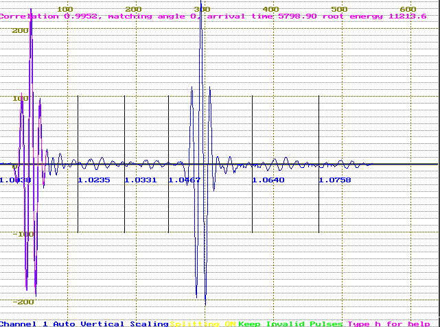
Figure 5 - Echo pulses after threshold extraction. An overlaid template appears on the left most pulse.
Interference between the sonar sensors or from other robot ultrasonics sources needs to be rejected for reliable operation. Sonar researchers (Jorg and Berg 1998, Peremans et al 1993) have employed pseudo random and Barker pulse coding with durations of 1 to 2 milliseconds that require the use of DSP systems to process the resulting echoes. The approach taken in this paper is simpler and consequently much faster to process. Each transmitter fires two precisely timed pulses with a time separation unique to the particular transmitter. The receivers can then identify echoes corresponding to their transmitter by searching for a correctly matching second pulse. By examining the maximum difference between two pulses with appropriate delay, very fast and sensitive detection can be achieved. Both amplitude and arrival times need to match between the two pulses for an acceptable maximum difference to be achieved. Delays of less than 0.5 msec can be discriminated, making the possibility of false identification very remote. This sensitive detection has a drawback - the effect of robot velocity gives rise to a Doppler shift in the double pulse separation. The current implementation has been designed to tolerate robot speeds up to 1.3 metres per second. Experimental trials found that double pulses were accepted for speeds to 1.0 ms-1. Speeds above 1 ms-1 were not tested.
Sonar Tracker Control
Each of the two sonar sensors’ panning angles is controlled independently whilst the firing of the transmitters is synchronised due to the hardware implementation. The sonar tracker has two simple modes:
(i) Object Searching - higher level commands define the search angle over which a sonar sensor scans. The sensors pans to the starting angle at 350 deg/sec, and then pans to the final angle at 90 deg/sec whilst firing repetitively. The largest amplitude echo that matches a template with a correlation coefficient higher than 0.85 is selected. This procedure aims to select, within the bounds set by the search angle range, an object for tracking that produces a single clear reflection whose echo pulse does not overlap with other object echo pulses.
(ii) Object Locking - from the initial pan angle supplied from object searching, the sonar sensor repetitively fires and from echoes, within a time of flight attention window, finds the bearing angle to the largest amplitude object. This angle is used as an error signal to control the pan angle so that the sonar sensor points to the object. The time of flight attention window is set to a fixed time before and after the previous object time of flight and enables range discrimination should multiple objects produce echoes. It also speeds up sonar data processing. A "no lock" situation arises when no objects are detected within the attention window. After a fixed number of consecutive "no locks", object locking is abandoned and a new search commenced. This allows for occasional loss of tracking due to, for example, people walking past the object. Changes in robot odometry orientation are employed to assist object locking.
Although the sonar trackers have been deliberately positioned on the robot to minimise crosstalk problems, it is still possible for both trackers to track the same object. To illustrate the interference rejection capability of the sonar trackers, an experiment has been devised to track a plane object at a range of 3.5 metres with both sonar sensors simultaneously whilst the robot slowly rotates as shown in Figure 6. This situation is unusual and has been deliberately contrived to demonstrate the crosstalk rejection capability of the sonar sensors.
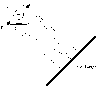
Figure 6 - Experimental arrangement for studying interference.
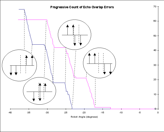
Figure 7 - Progressive count of tracker failures due to overlapping pulses.
As the robot rotates, each sonar sensor receives pulses from the other sensor that gradually shift past the pulses of interest. The crosstalk pulses are rejected by the delayed pulse subtraction verification technique described above. However when two pulses overlap, the arrival time cannot be determined by matched filtering due to pulse shape distortion and the sonar sensor reports a "no lock". The cumulative total of "no locks" are plotted against the robot angle in Figure 7 as the robot angle decreases from right to left. Overlap conditions are represented in the timing diagrams in the circular reliefs - up arrows represent front sensor pulses, down arrows represent rear pulses and dashed lines represent crosstalk pulses. For example, from -18 to -20 degrees the rear sensor first pulse overlaps with the crosstalk second pulse from the front sensor. The sonar sensors are 0.33 metres from the robot centre of rotation and the 2 degree overlap intervals correspond to 1 cm of movement of each tracker towards and away from the plane.
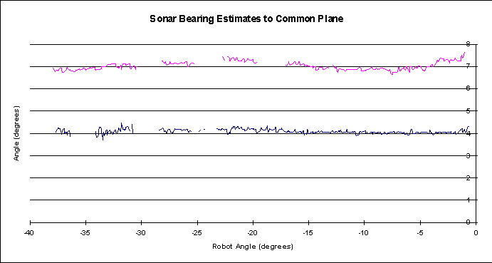
The sensor bearing estimates combined with odometry orientation are plotted in Figure 8 from the same experiment. An offset of 3 degrees has been introduced between the two angles to allow clearer presentation. The gaps in the data correspond to the pulse overlap conditions. It should be stressed here that overlapping pulses are usually a rare event and the results presented here are intended to illustrate the worst case scenario.
This section presents bearing angle results obtained from the sonar sensor across the full available beamwidth of the sensor. Note that the beamwidth available depends on range, object reflectivity and ambient air conditions. The angle to a plane at a range of 2.75 metres was measured with 200 readings at each 1 degree increment. The mean plus and minus two standard deviations of the angles are plotted in Figure 9. Although the discrepancies between different measurements are small, they are statistically significant. One obvious source of error is the optical encoder resolution of 0.18 degrees. Another source of error is air turbulence combined with temperature gradients. Sound propagation is refracted by speed of sound gradients resulting from temperature gradients. By observing the angle output in real time, significant variations up to 0.5 degrees lasting several seconds have been observed as people walk past the tracker (but not blocking the echoes). Placing a hot object, such as a cup of coffee under the air column of propagation results in large random angle and amplitude fluctuations.
In order to study this further, experiments were conducted in a laboratory where cold air draughts mix with the warmer air in the laboratory. The autocorrelation of the angle errors is plotted in Figure 10. A cyclic variation of errors of approximately 5 seconds is apparent in the angle errors. It is clear that the error spectrum is coloured and any future sensor error models should include non-white noise assumptions.
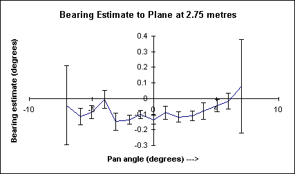
Figure 9 - Bearing angle measurements to a 2.75 m range plane. Mean, plus and minus 2 standard deviation errors bars are shown.
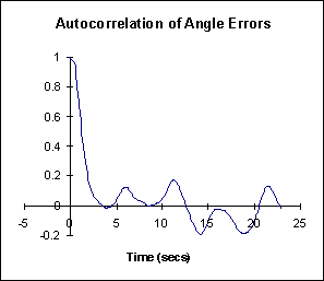
Figure 10 - Autocorrelation of 1000 bearing angle measurements - sampled at 10 Hertz from a plane at a range of 1.1 metres under reasonably turbulent conditions (angle standard deviation of 0.067 degrees).
Conclusions and Future Work
This paper has presented a new sonar system that can reject interference from other sonar systems using a simple double pulse coding scheme. The software check of validity of a double pulse requires little processing to implement since it involves just shifting and subtraction operations. The sonar system operates sufficiently rapidly for application to real time map building and localisation problems. The sonar sensor range and bearing errors are so low that ambient air conditions are the main contributing factor to errors. The effects of air turbulence and temperature gradients on sonar bearing estimation have been highlighted in this paper as a significant area for future research. Future work on real time directed sensing for map building and localisation will be pursued with the robot and sonar trackers.
Acknowledgments
This work is funded by a large Australian Research Council grant. The professional engineering work of Greg Curmi and Steve Armstrong are gratefully acknowledged.
References
Borenstein, J and Koren, Y 1995, "Error eliminating rapid ultrasonic firing for mobile robot obstacle avoidance", IEEE Trans. Robotics and Automation, Vol 11, No. 1 pp 132-138.
Budenske, J. and Gini, M. 1994, "Why is it so difficult for a robot to pass through a doorway using ultrasonic sensors?," IEEE Conference on Robotics and Automation, San Diego CA, pp. 3124-3129.
Chong, K and Kleeman, L. 1997, "Large Scale Sonarray Mapping using Multiple Connected Local Maps", International Conference on Field and Service Robotics, ANU December 8-10, pp. 538-545.
Jorg, K. and Berg, M. 1998, "Mobile robot sonar sensing with pseudo-random codes", Proceedings 1998 IEEE Conference on Robotics & Automation, Leuven, Belgium May, pp 2807-2812.
Kleeman, L. and Kuc, R. 1995, "Mobile robot sonar for target localization and classification", International Journal of Robotics Research, Volume 14, Number 4, pp 295-318.
Kleeman, L. 1996, "Scanned monocular sonar and the doorway problem", IEEE/RSJ International Conference on Intelligent Robots and Systems, Osaka, pp 96-103.
Kuc, R. 1993, "Three dimensional tracking using qualitative sonar," Robotics and Autonomous Systems, vol. 11, pp. 213–219.
Lee, D. 1996, The map-building and exploration strategies of simple sonar-equipped mobile robot, Cambridge University Press.
On Time Informatik GMBH 1995, RTKernel 4.5 Real-time multitasking kernel for C/C++ User’s Manual.
Peremans, H. Audenaert, K. and Camperhout, J. 1993, "A high-resolution sensor based on tri-aural perception," IEEE Transactions on Robotics and Automation, vol. 9, pp. 36-48.
Performance Motion Devices 1995, "Advanced multi-axis motion control chipset MC1401", Concord MA 1995.
Stevens, A., Stevens, M. and Durrant-Whyte, H. 1995, "‘OxNav’: Reliable autonomous navigation", IEEE International Conference on Robotics and Automation, pp 2607-2612.
Tsubouchi, T. 1996, "Nowadays trends in map generation for mobile robotics", Proceedings IROS’96, Osaka Japan, pp 828-833.
Yata, T., Kleeman, L. and Yuta, S. 1998, "Fast bearing measurement by a single ultrasonic transducer and its application to mobile robot wall following", Proc. IEEE International Conference on Robotics and Automation 1998, Leuven, Belgium, pp. 1590-1596.